Port letters describe intended connections, but they should always be checked against the exact component drawing. A wrong pilot or drain connection may not be obvious from the valve's external appearance.
Start with the working ports
P commonly identifies pressure supply, T tank return, and A and B the actuator connections. Trace each one through the drawing in neutral and energized positions. Multiple tank connections or internal passages can make the physical arrangement less intuitive than the letters suggest.
Identify control connections separately
X and Y are commonly used for pilot supply and pilot drain, but conventions and optional configurations vary. An external drain is not necessarily permitted to see the same pressure as a main work port. Obtain the allowable pressure for each connection.
Confirm orientation at installation
A port label on a manifold drawing may be shown from a different viewing side than the valve's mounting face. Use locating features, drawing views and port coordinates to confirm orientation. Do not rely on which connector happens to be on the left in a photograph.
Practical checklist
- Use the supplied model's symbol and mounting drawing.
- Trace all pilot and drain passages as well as working ports.
- Check individual port-pressure limits before connecting lines.
Discuss your application
Explore related hydraulic products, or send JIUDING your model code and application details. Include the circuit drawing and the operating conditions relevant to the checks above so the required configuration can be reviewed.
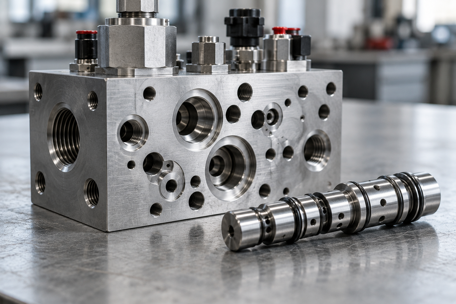
Cover image: AI-generated editorial illustration, not a model-specific product drawing or a photograph of a JIUDING facility.